PI4CC
|  |
Bandpass filters for PI4CC
13-may-2017 Start selling PCB's for this project.The PCB's are on stock and ready for instantly shipping.
Contesting is all about the ability to listen. Undesired strong signals, even out-of-band, can cause undesired QRM due to overloading receivers. Harmonics that end up in the next higher bands are even worse. With our current coax stub filters we can suppress small frequency-slices (notches), but the majority of the spectrum passes unattenuated. So, we embarked on a project to remove all signals that are outside the bands of interest.
This bandpass filter project aims at serveral goals:
- Ability to handle high power (1 kW)
- Low insertion loss to avoid heat build-up in order to avoid a cooling fan.
- Adjacent band attenuation > 80 dB.
- Easy reproduction, modular setup.
- Rugged, stable housing.
Literature suggested a combination of Chebyshev and Cauer characteristics. The design was done by Elsie, followed by simulation with LT spice. We settled on a 4-pole induction-coupled Chebyshev band pass filter followed by a single Cauer stage to provide a notch for the adjacent band below. LT spice showed a next band rejection of 80 dB. Note that capacitor-coupled Chebyshev stages would have the "tail" on the "wrong" side for this purpose. The picture below is a combined LT-Spice simulation of 6 filters.
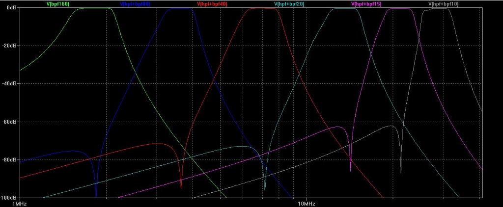
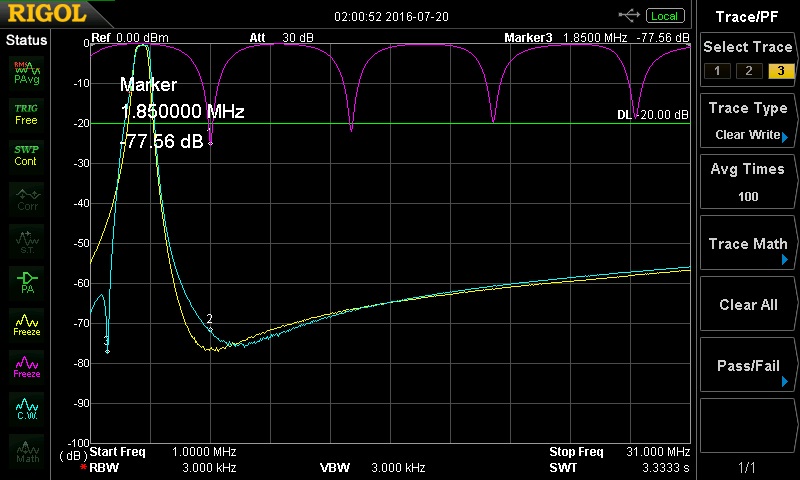
Purple line shows the 80m coax-stub notch filter.
Yellow line shows the 4-pole Chebyshev filter.
Blue shows the same filter including the Cauer stage (a notch on 160m).
The second harmonic (which sits in the 40m band) has about 38 db attenuation and 160M will be > 70 db suppressed as compared to the current coax stub notch filter.
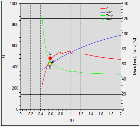
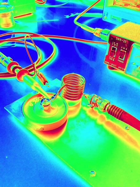
Finding optimum Q experimentally by variation of length, diameter and wire thickness is next to impossible. A mathematical approach is unavoidable. As proper calculations are far more complicated than the formulas found in textbooks, software (incuding real-time animation) was written to arrive at the desired trade-offs between size, wire, material and heat dissipation. The picture shows diameter, L/D and surface temperature for a given self-induction, material, wire thickness and RMS current. This model is to be published in due course.

Suitable capacitors are being sourced from American Technical Ceramics www.atceramics.com. ATC provides component and custom integrated packaging solutions for the RF, microwave and telecommunications industries.
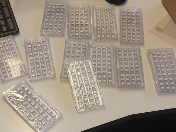
Most C's are received. Now it time to design the PCB.
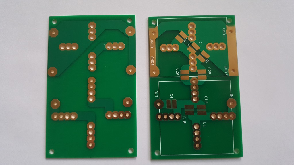
The PCB.
A universal PCB is developed. This will held all combinations of all type of filters. You will need 5 PCB's per filter.
We will sell PCB later after thoroughly tests.
If you have intrest in a set of PCB's, send een email via this form.
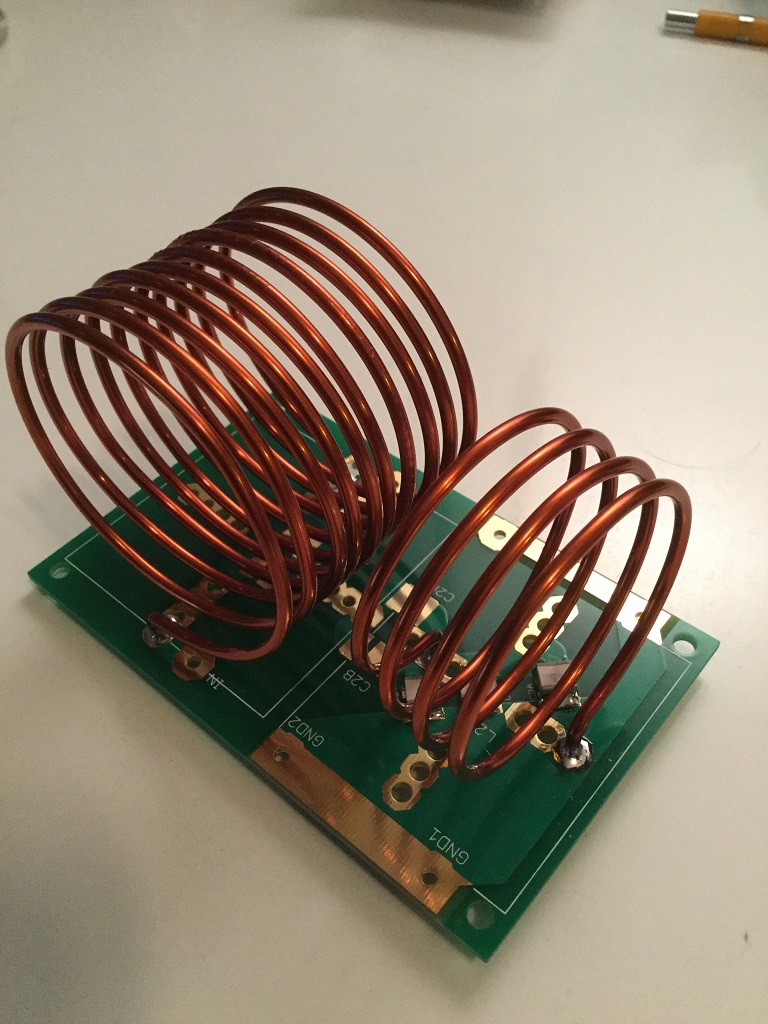
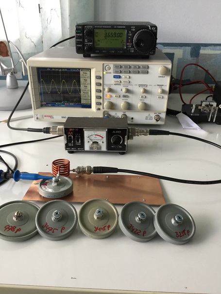
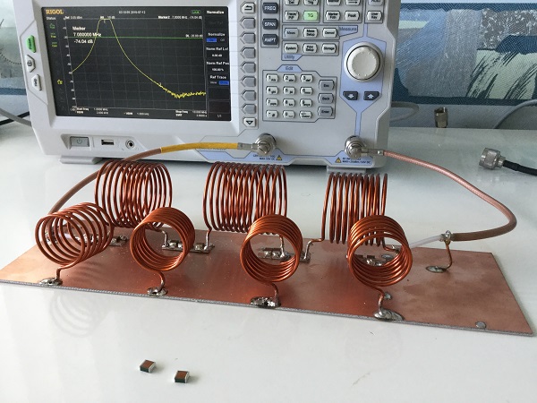
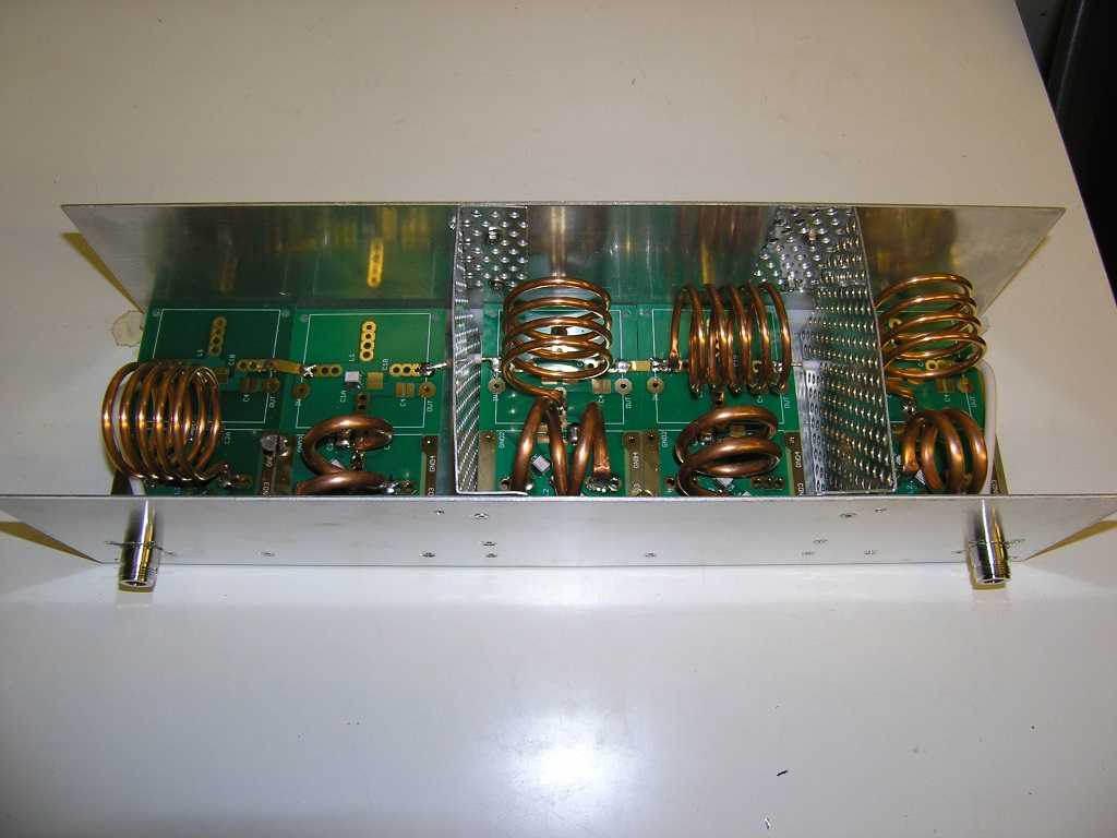
The PCB's has arrived and its time to build a filter.The first filter section assembled.
Five of these units will form the bandpass filter
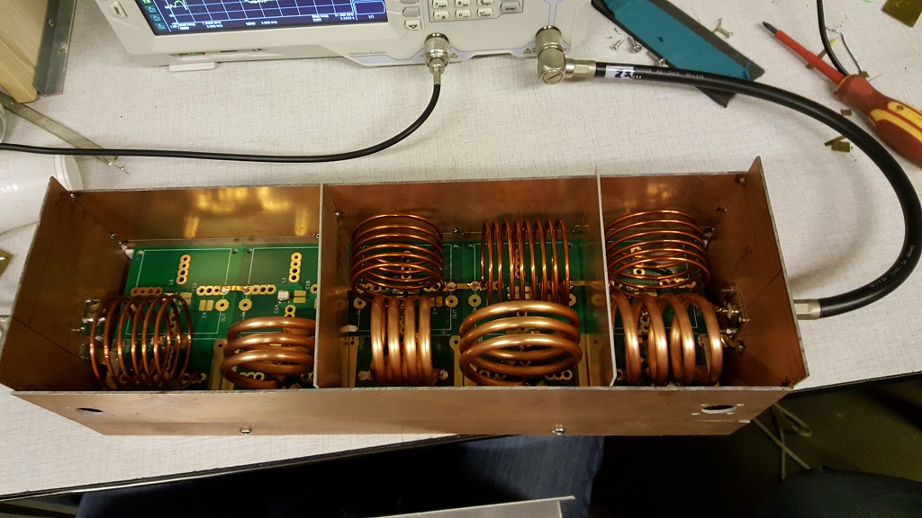
A prototype RF wise housing with the 40m modules inside.
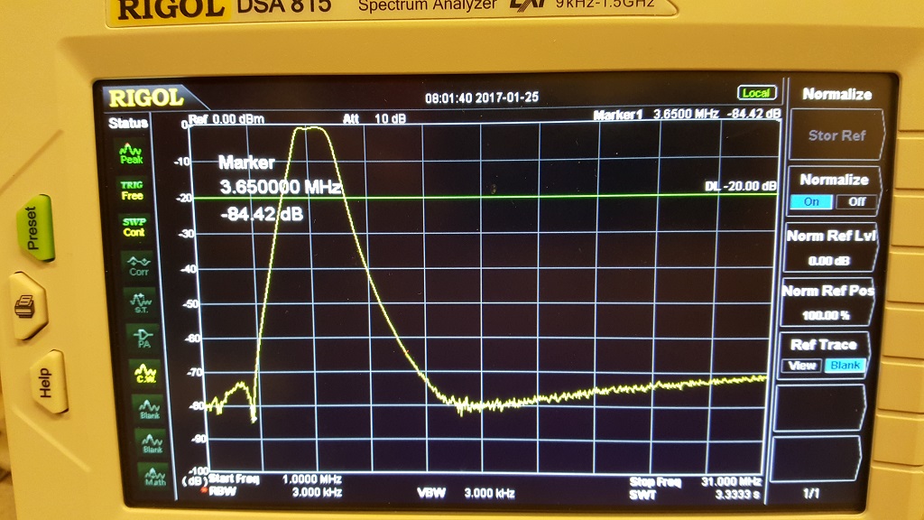
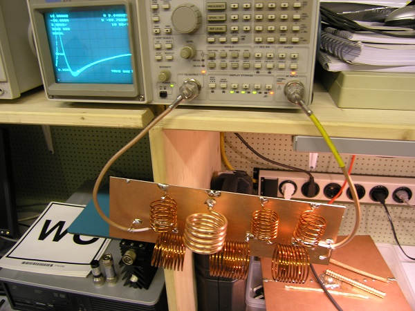
A sweep on the 40M filter. A nice > 80dB recejction of 80M band and above 40M 80dB on 20M slowly going up to 70db rejection on 10M.
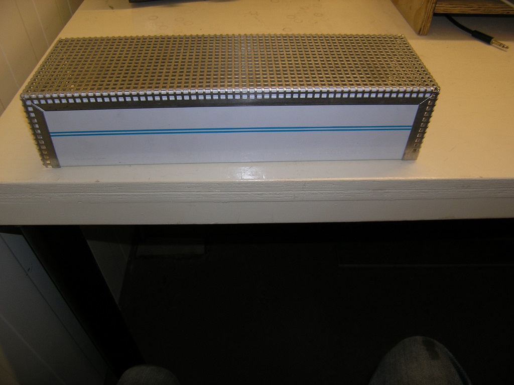
Finally we found the correct way to make the housing. We are inspired by Hammond, but we make the cover of perforated aluminum. A few photo's with contruction details are here.
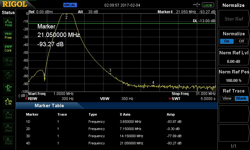
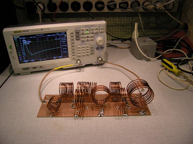
The same 40M bandpass filter but in the new housing and fine-tuned.
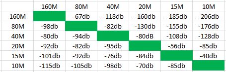
Look add those figures.
In band < 0,3 dB loss and > 77dB on any other contest band!
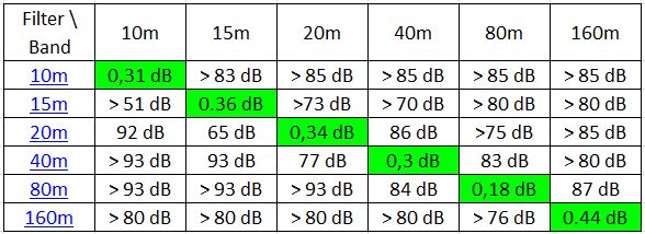
A overview of each filter in a table. A plot of each filter is here
During the PACC 2017, we tested our high power band pass filters on 15M - 20M - 40M - 80M
The filters passed the contest and did there job without any problems.
A look at the 15M final version.
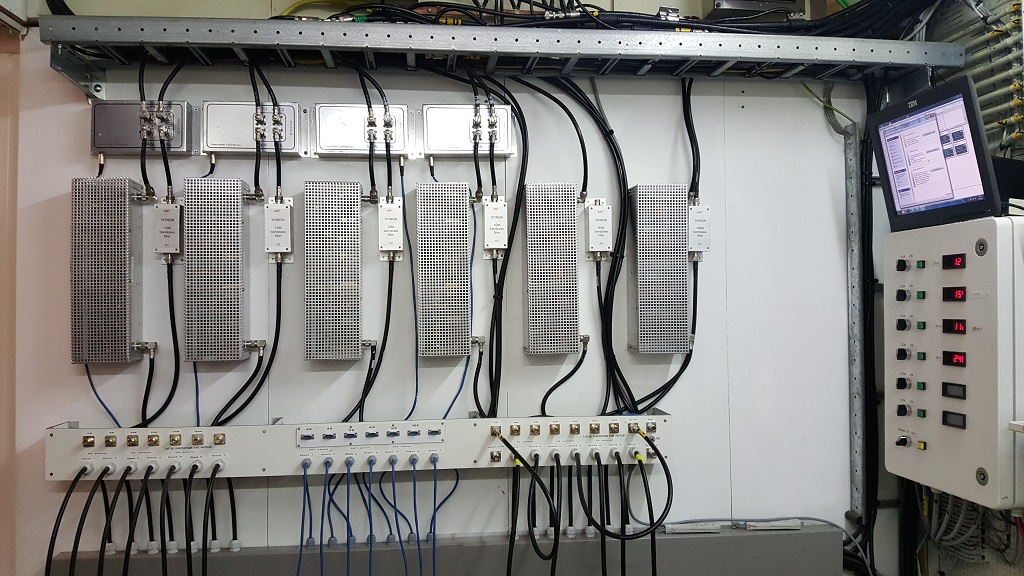
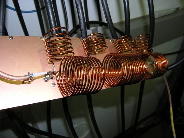
A view of the 6 filters installed at our patch panel.
From top to the bottom: Stackmatch/power splitter, hp-filter + W3NQN filter, coax/rotor patch panel.
On the right side our rotor control cabinet.
It not easy job to to build a good filter. You will need some skills, tools and patience to fulfilll the job!
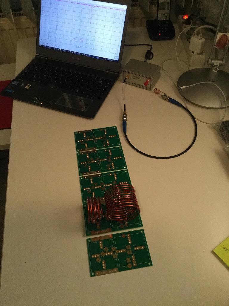
Needed tools are at least a VNA to trim the coils. Prefferd a spectrum analyser to check the performance.
A work branche to modify the enclosure, to drill the holes and do some metal works.
To get an idea about the cost for a 10 - 80M filter :
- The C's per filter vary between 45 and 81 euro.
- An enclose 26 euro.
- A set of PCB's 25 euro.
- 2 female N connectors 10 euro.
- Some copper tube.
If you still want to continue to build your own filter(s), have a look here
Last update 31-may-2017